Salvaging Water-Damaged Equipment
By Grainger Editorial Staff 7/23/20
Techniques and Tools to Determine Repair or Replacement
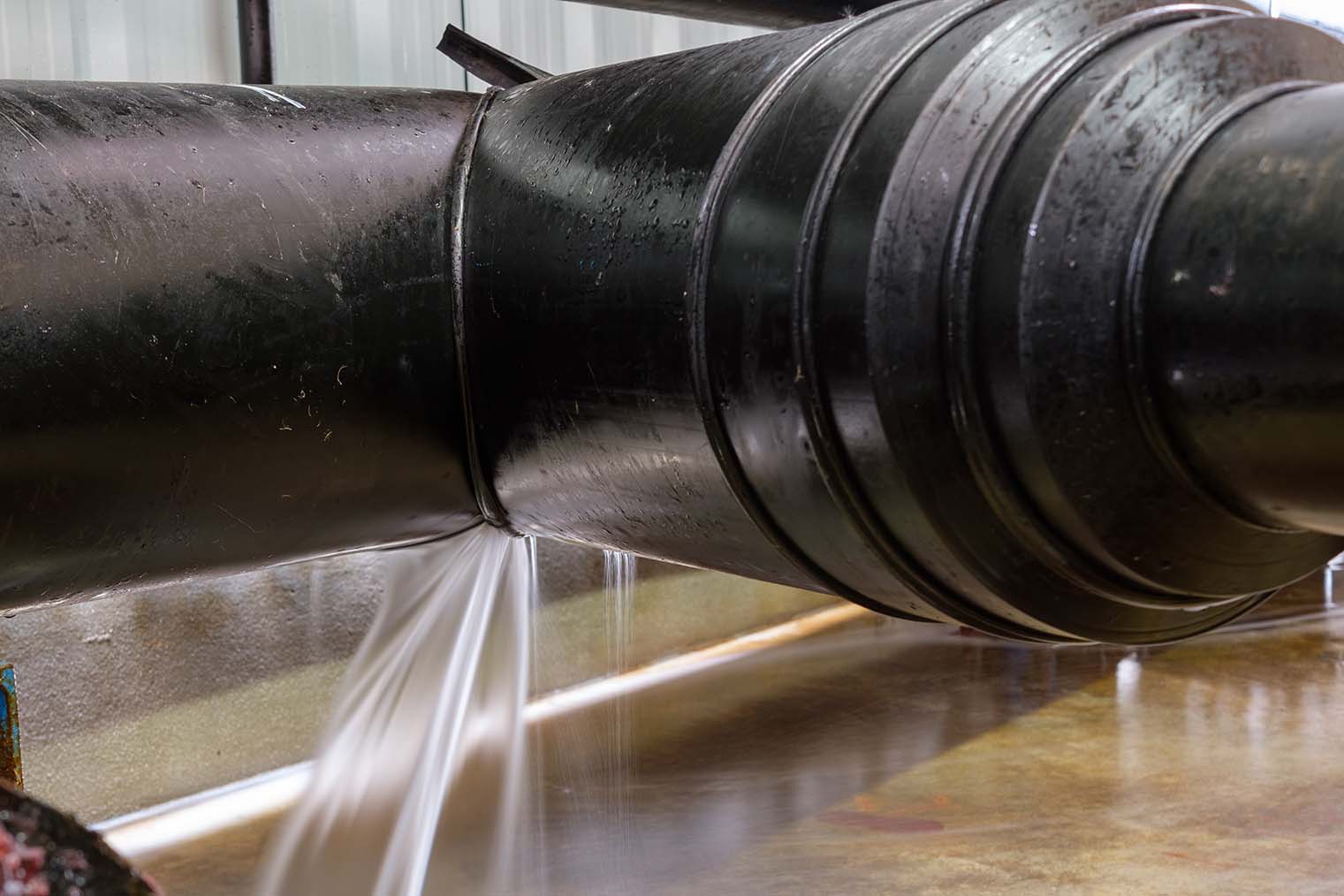
Water is one of most serious factors in the breakdown of electrical equipment. Typically, damage is gradual and happens through condensation, normal rainfall, ground water, or slow seepage from industrial processes. However, it can also be catastrophic from severe storms, flooding and burst pipes to other sudden failures. Regardless of the source, you can help prevent equipment damage by effectively removing moisture from electrical insulation.
The key to the successful recovery of water-exposed equipment is the ability to actually dry the equipment before any use takes place. But keep in mind that the main factor in the failure of a product’s insulation system, over time, is heat. Heat will slowly deteriorate the physical properties and eventually break down a component’s insulation system, resulting in failure.
So, when drying water-damaged equipment it’s important that temperature be carefully controlled in order to prevent thermal deterioration. Maximum drying temperatures on windings should not exceed 194°F, measured by thermometer.
Drying and Testing—Methods for Commercial Equipment and Wiring
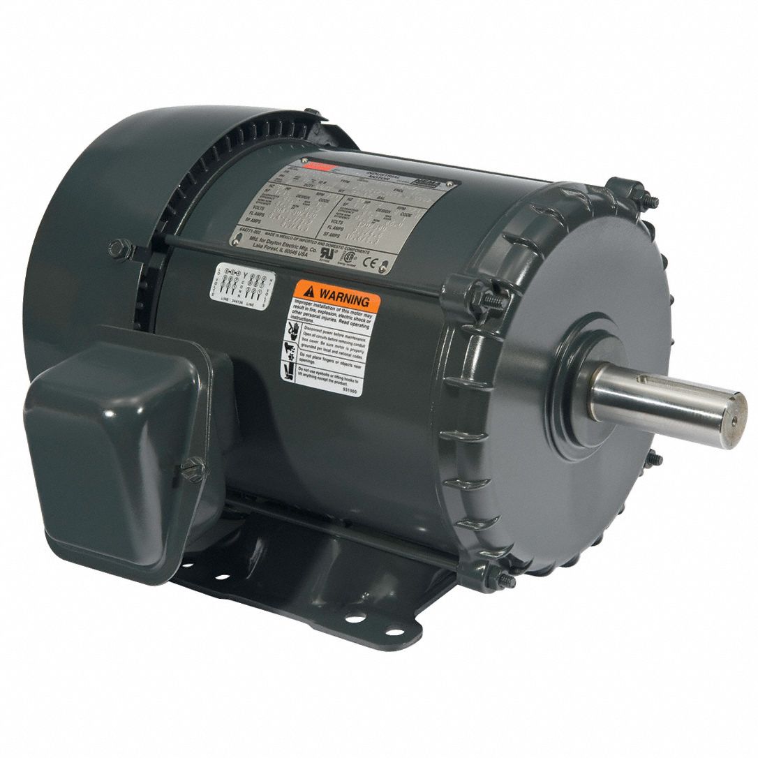
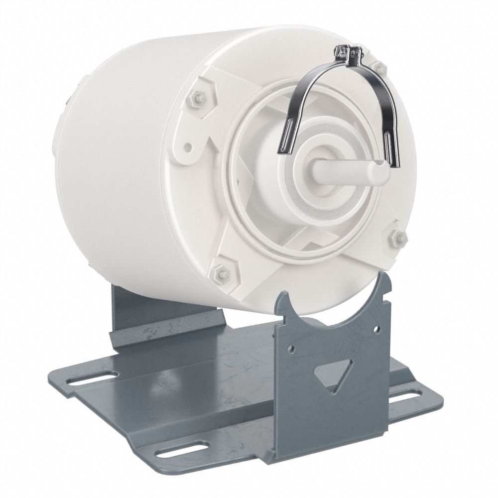
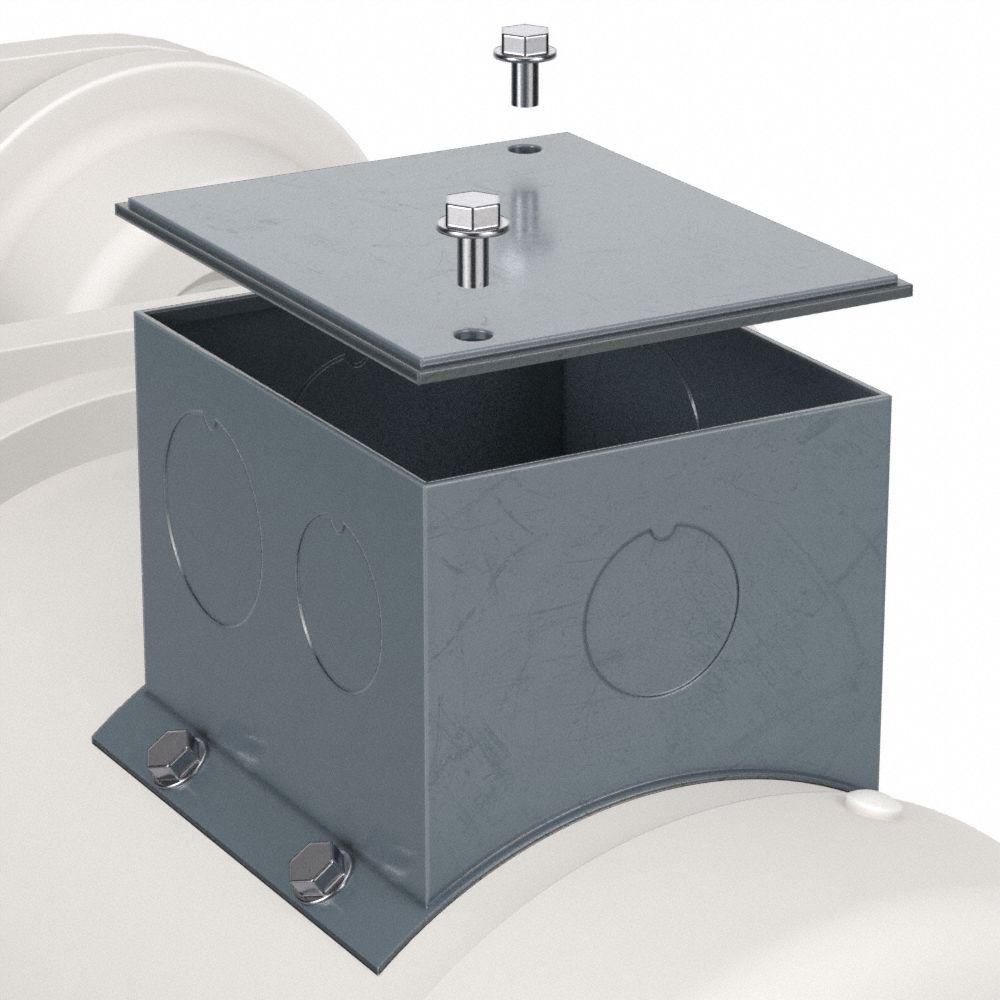
Effective ways of drying include ovens with suitable temperature control and air circulation, banks of infrared lamps or electric heaters. Motor windings should be removed from their housings, or the cases opened as much as possible. Wiring can be dried by gently blowing warm air through the conduit, or removal and re-installation if necessary. Dry air is preferable, as it will remain essentially captured after the process is complete. Any humidity present in the air can leach back into the insulation.
An insulation tester, or megohmmeter, is used to monitor the components’ progress and drying success. Megohmmeters are designed to detect insulation deterioration caused by moisture, corrosion, dirt or normal aging. Be careful not to use a “high-pot” as they are specifically designed to break down marginal equipment.
In the drying procedure, “breakdown” is what we are trying to avoid. To that, be certain that the megohmmeter has what is generally called a “kilohm” range. Simple insulation testers are designed so that electricians can perform basic tests for “shorts” and “opens”, but may have no additional functions. Those types of meters may have only a high voltage range and a “continuity” range. These two ranges provide measurements on the megohm (for “shorts”) and ohm (for “opens”) scales, but leave a gap in between. It is this mid-range, in thousands of ohms, that is critical to the drying process.
Resistance
Insulation resistance is inverse to the amount of “leakage” current that flows to ground through the insulation. As moisture is gently driven off, leakage diminishes and resistance rises. This rise can be monitored with the right megohmmeter until it reaches, and maintains, acceptable levels. Insulation is not adequate until it is at least in the megohm (millions of ohms) range.
Insulation testing will not damage a reasonably sound insulation system. However, after a flood or severe water damage, thoroughly saturated insulation may measure only a few thousand ohms. In this condition, the sudden application of a “high voltage” (250 or 500 Volts) test could cause localized damage, such as a pinhole. This would require extensive repair, and possibly a motor rewind. The sensible use of a kilohm range avoids this problem.
Choosing the correct megohmmeter
The hand-held Megger 2MY17 is suited for this application.
- The kilohm selection initiates a test at only 5 Volts, and measures from 10 Ω to 1 MΩ.
- The increase in resistance can be periodically checked at convenient intervals throughout the drying process. This can typically be 1 – 2 hours, but can be customized to fit the application or the operator’s workload.
- Test lead hookup can also be customized. For example, all circuitry (“hot” and neutral or all three phases) can be “ganged” to the output side of the tester, and connected with a single alligator clip lead. The “return” or “low” side is then completed by connecting the other lead to casework or ground.
Collecting the entire test item into a single test will give a “worst case” result. Because this isn’t a troubleshooting application, it shouldn’t be necessary to “sectionalize” the test item. If the equipment has suffered a breakdown, such as by shorting to ground, drying will not substantially improve the reading. Therefore, time can be saved by aborting what might otherwise be a long drying process.
Remember, readings should not be taken in standardized intervals because an insulation test will capacitively charge the item being tested. Taking readings at 1-minute and then 30 second intervals may result in false conclusions. Once resistance has passed 100,000 Ω (or 100 kohm) high voltage ranges may be used. Drying should continue until resistance reaches an acceptable level that’s high in the megohm range.
For full recovery to pre-damage serviceability, much higher values should be the goal. The 2MY19 will measure to 1000 MΩ. It is advisable to restore equipment to an “overrange” level, in order to assure continued service. These practices will implement restoration of commercial equipment and wiring operating on common 120, 240, and 480 circuits.
Restoring “Heavy Duty” Equipment
For high-capital “heavy duty” equipment operating at higher voltages, two enhancements are recommended: increased test voltage and expanded measurement range.
Deteriorated insulation opens up new leakage paths as voltage stress is increased, causing resistance readings to drop. Since water damage creates almost limitless current pathways, any restoration process must assure that full voltage response has been restored. In addition, higher rated equipment will have commensurately higher insulation resistance. An expanded range is necessary for the full restoration of equipment where initial values may have been in the teraohm (literally, thousands of thousands of megohms) range.
Make sure you use a tester that offers selectable test voltages to 5kV and measurement to 15 tera-ohms.
Because higher voltage test models are designed for advanced predictive maintenance applications rather than proofing of basic commercial wiring, they do not have the requisite low voltage/low resistance ranges that are critical in restoration operations. It is necessary to be equipped with an additional tester offering the low voltage/low resistance range feature.
Standard commercial equipment up to 480 V might also be subject to more rigorous preventive/predictive maintenance regimes, where resistance values are measured and recorded into the Gig-ohm range. An over-range indication on a 1 GΩ model certainly indicates that equipment has been adequately restored and can be counted upon for the foreseeable future. But if prior records are being matched or “like new” condition is the goal, it is advisable to have a tester with expanded range.
The 1 kV tester family use a fully enhanced versions that measures up to 20 and 200 gigohms respectively. If the restoration process requires additional electrical tests to those already described. These testers include measurement ranges for voltage, current and resistance will cover the entire series of tests with a single instrument. These functions include a millivolt input range, so that a variety of transducers can be used to enable the tester to perform additional measurements including temperature, air speed or air pressure.
Restoring Telecom and Datacom Applications
Applications to telecom and datacom equipment can be further addressed with the Megger model 1PKC7, as this model offers the lower test voltages commensurate with this application. Standard power equipment can still be tested at 250, 500, and 1000 V, and additionally, telecom/datacom testing can be performed at a selectable 50 or 100 V. A capacitance measurement function (to 10 μF) enables qualified fault location of “shorts” and “opens” on twisted pair, if the length of the circuit is known. Capacitance for the known length is calculated, and if the measured capacitance falls short, the ratio of the two indicates the distance to a short or open.
An additional feature available on some of the newer testers on the market is the ability to store and download test results. With this capability, third-party compliances (such as insurance companies and OSHA) can be assured. Test results are recorded directly from the instrument onto a test report, eliminating potential errors in transcription and interpretation.
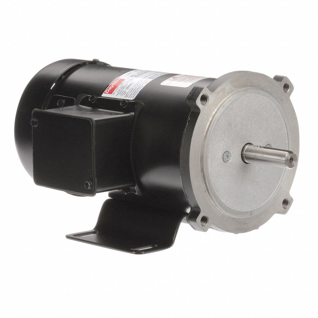
Using a Motor and Phase Rotation Tester
All of the procedures above are performed on de-energized equipment. When removing and or repairing equipment, always use proper shut down and lock out tag out procedures. At the conclusion of cleaning, drying and restoration practices, it is easy to overlook proper phase rotation in reconnecting equipment. Use a motor and phase rotation tester that is self-contained, capable of performing all the indication and identification necessary for correct 3-phase hookup.
- Two sets of 3-phase alligator clip leads identify rotation on the live-line and motor sides respectively.
- The live-line (red) leads are clipped at random to the energized 3-phase conductors, and the selector set to LINE.
- A center-position null meter deflects either to CORRECT or INCORRECT.
- If CORRECT, the conductors are tagged in the same sequence as the tester’s leads, indicating correct phase rotation.
- If INCORRECT, switch any two leads and repeat the test to verify correct rotation.
On the motor side, the test is de-energized.
- The alternate trio of black leads are similarly connected to the motor contacts as the reds were to the phase conductors, and the selector set to MOTOR.
- Power for this test is provided by the operator and a lone C-cell.
- The operator manually turns the shaft, about a quarter turn, in the direction (clockwise or counter clockwise) in which the motor is intended to operate.
- The battery provides the energy to drive the pointer to either CORRECT or INCORRECT. Again, in the case of the latter, any two leads are switched and the test repeated to confirm correct rotation.
- With both the power feed and the motor now identified and tagged, connection can be made at any convenient time in the reconstruction process, and when energized, the motor will turn in the desired direction.
- This simple operation precludes the guesswork that could otherwise result in damage should the motor turn in the wrong direction.
Water damaged equipment doesn’t always have to be replaced. With the correct tools and a bit of insight into troubleshooting, most components can be repaired and up and running again at minimal cost.
The information contained in this article is intended for general information purposes only and is based on information available as of the initial date of publication. No representation is made that the information or references are complete or remain current. This article is not a substitute for review of current applicable government regulations, industry standards, or other standards specific to your business and/or activities and should not be construed as legal advice or opinion. Readers with specific questions should refer to the applicable standards or consult with an attorney.


CONNECT WITH US


SIGN UP FOR EMAIL
Get more great content in your inbox.