The Top 5 Locations to Improve Building Energy Efficiency
By Grainger Editorial Staff 1/1/17
A significant amount of energy loss is actually temperature related. Hot or cold air leaks from a building are obvious examples. It took energy to condition that air, and when it dissipates due to a leak, you’ve wasted that energy.
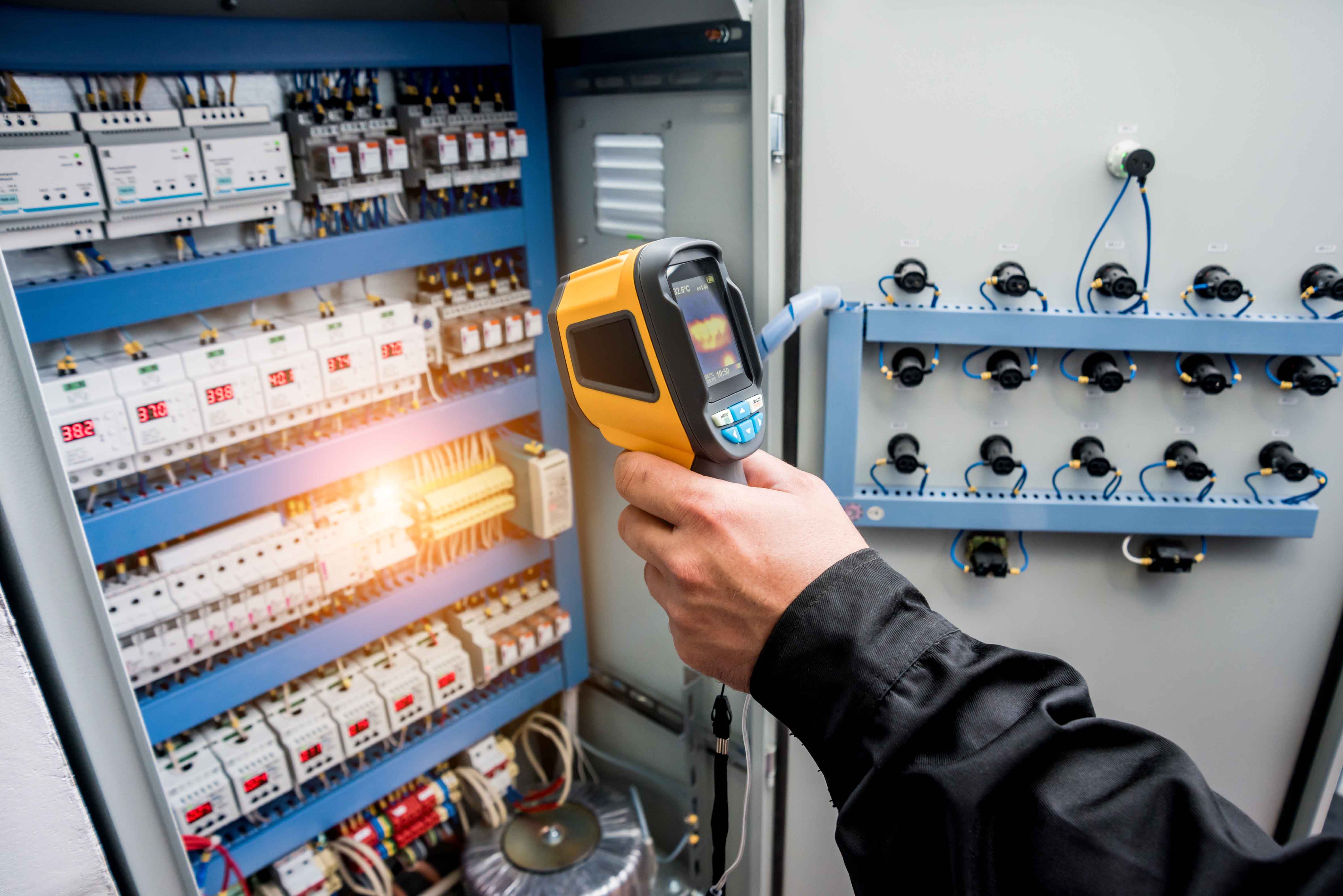
Many other systems and pieces of equipment also manifest their wasted effort/energy in terms of heat. Motors, pumps and electrical boxes will generate heat and lose energy efficiency as they begin to fail. Unlike regular digital cameras that capture images of the visible light reflected by objects, thermal imagers create pictures by measuring infrared energy or heat. The thermal imager then assigns colors based on the temperature differences it measures.
With a small amount of training, most people can readily spot abnormal temperatures and follow the heat trail to energy waste. The technique works best when used by people who already possess a good working knowledge of the structures and systems being scanned and can better interpret the temperature variances they see on camera.
A typical scan can show energy saving opportunities of up to 15 percent, with varying degrees of repair investments. Thermal imaging experts suggest that building owners, building managers and/or facilities engineers inspect the following systems to identify energy losses:
Building Envelope
“Building envelope” refers to the building structure as well as the climate controls within it. The envelope is what separates the outside environment from the inside, and it’s frequently imperfect. The key to building envelope inspection is that since the degree of temperature variance may be very small—one or two degrees, the best time to scan is during a heating or cooling season, when the outside temperature is at least 10°C higher or lower than the inside temperature.* Similarly, beware of thermal loading, or other environmental factors, which could mask or distort potential problems. For instance, don’t scan an exterior wall when the sun is shining on it. When performing roof scans, make sure that the roof has been dry and free of water or ice. The best inspections should be performed on clear, windless evenings after dusk, or before dawn, when thermal differentials in the roofing materials are in a transient state. (Be aware that not all roofs can be effectively inspected using infrared thermography.)
What to Scan
- Roofs. Wet roofing insulation loses its R-rating. Scan the roof surface and follow temperature differences to possible entry/exit areas for conditioned air. Note: Spot repairs are less expensive than replacement, and old roofs are often a challenge to dispose of because of their contents.
- Walls between conditioned and unconditioned spaces, including outside walls. Concentrate on the top and bottom of conditioned spaces and also look for indications of missing or wet insulation.
- Construction Joints and Connections. For example, at floor slabs that extend outdoors, there are often heating or cooling losses by conduction through the slab.
- Penetrations of the Building Envelope. (pipes, conduits, chimneys, etc.). Uninsulated gaps often exist around roof and wall penetrations.
- Door and Window Frames and Seals. Look for leaks due to poorly fitting doors and windows, but bear in mind that spot repairs to major losses such as roof leaks usually offer faster payback than fixing door and window seals.
Anticipated Savings:
The Department of Energy estimates that following up on the findings of an energy audit of a building’s envelope saves most facilities at least 15 percent on energy bills.
HVAC System
The heating, ventilation and air conditioning (HVAC) system is usually one of the biggest areas of energy consumption within a facility.
What to Scan
- Ductwork and Registers. Even the highest-rated HVAC system wastes energy without a well-sealed duct system. With infrared technology, one can see the thermal pattern of air loss or gain in ducting and also monitor registers to determine whether heating or cooling output is optimal.
- Fans and Blowers. These mechanical elements are, of course, motor driven. For more details about what to look for in motors, see “Motors and Generators” below. In fans and blowers, mechanical imbalance will manifest itself in overheated bearings and other components. Thermal images of these systems can also identify shaft misalignment in couplings between the motor and fan.
- Electrical Connections. A loose or corroded connection increases resistance at the connection, resulting in overheating.
Anticipated Savings:
Studies indicate that commercial buildings with constant-air volume systems often experience energy losses from air leakage of as much as 33 %. Also, studies indicate that air-supply temperature differentials due to conduction losses can be as great as 6 °C (10.8 °F) or more.1 Considerable savings can be achieved in with duct-sealing and insulation remedies.
Motors and Generators
Electrical motors also use a significant amount of energy in a facility. Overheating and malfunctioning motors and generators tend to indicate mechanical or electrical inefficiencies that can lead to more energy use and ultimate failure. Since generators are, in a sense, “reverse motors,” diagnostics are similar for both kinds of units.
What to Scan
- Airflow. In fan-cooled motors, a restricted airflow will cause general overheating manifesting itself on the entire housing.
- Electrical Unbalance. The usual cause, a high-resistance connection in the switchgear, disconnect or motor connection box, can usually be pinpointed by an infrared inspection and confirmed using a multimeter, clamp meter or a power quality analyzer. Scan the components of rotating equipment, especially the bearings and shaft. Watch out for shiny metal that can throw off a thermal reading.
- Bearings. When thermal images reveal bearing housings with abnormally high temperatures, either lubrication of the bearing or its replacement is called for.
- Insulation. Look for higher than normal housing temperatures in areas associated with windings.
- Electrical Connections. As with electrical connections in HVAC systems, look for loose or corroded connections that increase resistance.
Anticipated Savings:
With motors and generators, specific energy losses are usually of less consequence than failure of the unit. The impact of a motor or generator failure will be contingent upon the nature of the enterprise and the system(s) affected. That said, the two best ways to reduce motor energy expenditures are to:
- Keep motors well maintained/operating at maximum efficiency
- Size them appropriately and operate at constant speeds. Doing this for a period of time will yield incremental energy savings, after which you can re-invest in motor controls that will significantly reduce energy usage.
Steam Heating Systems
Today, steam systems are more common in industrial settings than commercial settings, but some commercial buildings still use them for central heating.
Where to Look and What to Look For
- Steam Traps. Check traps using both thermography and ultrasonic testing. Each technology works better than the other for certain traps and trap configurations.
- Radiator Coils. Check for leaks by conducting inspections similar to those of HVAC ducts.
- Steam Lines and Valves. Look for telltale signs of leaks and blockages and for blow-by at valves that are supposed to be “closed.”
- Condensers. Look for leakage of outside air, which reduces the condenser’s vacuum, thereby decreasing its efficiency.
Anticipated Savings:
In a 100-psig-steam system, if a medium-sized trap fails, opening it can waste about $3,000 per year.
Boilers
Boilers, of course, are the heart of steam and hot water heating systems.
What to Scan
- Refractories. Thermography makes possible in-service monitoring of the condition of refractory linings.
- Leakage of Outside Air. This condition is difficult to pinpoint with diagnostic technologies other than thermal imagers but can lead to substantial inefficiencies.
- Boiler Casing Insulation. Look for heat loss from damaged insulation.
- Fan Motors. As with motors in other applications, check for impeded airflow, electrical unbalance, overheated bearings and failing insulation.
- Pumps. Look for hot bearings, leaking seals and, as with fans, motor faults.
- Valves. Thermography can identify blocked valves that are nominally open and leaking valves that are nominally closed.
- Electrical Connections. As with other kinds of systems, look for loose or corroded connections that increase resistance.
Anticipated Savings:
In boilers, major energy losses— those associated with stack losses as well as radiation and convention losses—typically represent 10 to 20% of fuel input, depending upon fuel type. Insulation and boiler economizers can reduce these losses. 2
Electrical System
Many people don’t realize that electrical systems can actually waste money. As components degrade and resistance increases, incremental waste can occur.
What to Scan
- Distribution Panels. Check for unbalance in circuits and loose and corroded connections at breakers, contacts, fuse clips, busses, etc.
- Transformers. Monitor high- and low-voltage bushing connections, cooling tubes and cooling fans and pumps. Look for overheated connections, comparatively cool cooling tubes and hot or cool pumps. Be aware that if the temperature of one electrical leg on a transformer is significantly hotter than the others, that leg may be failing.
- Lighting Control Circuits. Check all wiring splices and connections at fuses, switches, and fixtures. Be aware also that thermography can also be used to monitor low-voltage control circuits.
Anticipated Savings:
According to some estimates, lighting accounts for about 20% of all electricity use in the U.S. and more than 40% of electricity use in offices, stores, and other commercial buildings. While complete retrofits of lighting systems are producing significant returns on investment, keeping lighting controls (time clocks, photo sensors, occupancy detectors, etc.) operating properly will help save energy.
Conclusion
Thermal imagers have come down so far in price that most facilities can recoup the cost of purchase in terms of energy savings within a relatively short period of time. Incorporating this practice into regular maintenance adds a host of efficiencies to a maintenance team as well as helping them identify and prevent expensive electro-mechanical failures.
* ASTM Building Standard C 1060-90 Appendix X2.2 (Standard Practice for Thermographic Inspection of Insulation Installations in Envelope Cavities of Frame Buildings) states that a minimum temperature differential of 10 °C (for a period of at least four hours prior to inspection) is preferred for infrared inspections of frame construction. ISO 6781 5.1a (Thermal insulation—Qualitative detection of thermal irregularities in building envelopes—Infrared method) states that: For at least 24 hours before the start of the examination, and during the examination, the air temperature drop across the building envelope shall be at least 10 °C.
- See, for example, the white paper found at http://energy.lbl.gov/ie/pdf/LBNL-44221.pdf entitled: "Duct System Performance and Energy Losses in Large Commercial Buildings," written by researchers at the Lawrence Berkeley National Laboratory.
This information is from the Canadian Office of Energy Efficiency.
Source: Fluke Corporation
![]()
The information contained in this article is intended for general information purposes only and is based on information available as of the initial date of publication. No representation is made that the information or references are complete or remain current. This article is not a substitute for review of current applicable government regulations, industry standards, or other standards specific to your business and/or activities and should not be construed as legal advice or opinion. Readers with specific questions should refer to the applicable standards or consult with an attorney.


CONNECT WITH US


SIGN UP FOR EMAIL
Get more great content in your inbox.